
Two gearboxes can share the same torque rating on the nameplate and still perform completely differently once installed, because the nameplate rating assumes a uniform load running a limited number of hours a day. Real factory equipment rarely works that way. Service factor is the multiplier that closes that gap between catalogue rating and real world duty, and skipping it is one of the fastest ways to turn a gearbox that looked correctly sized into one that fails within a year.
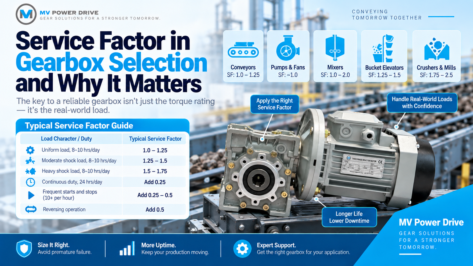
What Service Factor Actually Means
Service factor is a ratio between a gearbox’s catalogue capacity and the application’s actual required power. If your process needs 5 kW of output power but the duty cycle is demanding, you do not select a gearbox rated for exactly 5 kW. You select one rated for 5 kW multiplied by the appropriate service factor, so the gearbox has headroom to absorb shock loads, extended running hours and repeated starts without the gear teeth and bearings wearing out faster than expected.
The standard reference for this comes from AGMA (the American Gear Manufacturers Association), whose service factor tables have become the practical industry benchmark that most gearbox manufacturers, including the NMRV and WP series MV Power Drive supplies, design their capacity ratings around.
Service Factor by Load Character and Duty
| Load Character | Typical Service Factor |
|---|---|
| Uniform load, 8-10 hrs/day | 1.0 to 1.25 |
| Moderate shock load, 8-10 hrs/day | 1.25 to 1.5 |
| Heavy shock load, 8-10 hrs/day | 1.5 to 1.75 |
| Continuous duty, 24 hrs/day | add 0.25 to the value above |
| Frequent starts and stops (10+ per hour) | add 0.25 to 0.5 |
| Reversing operation | add 0.5, or specify a reversing rated unit |
These figures follow AGMA 6010 style guidance and are a starting reference, not a substitute for checking your specific gearbox manufacturer’s rated capacity tables, since some catalogues set their baseline service factor differently.
Typical Service Factors by Equipment Type
Different driven equipment carries characteristically different load profiles, and the application itself is often a faster way to estimate service factor than trying to classify shock level in the abstract:
- Centrifugal pumps and fans, uniform load: around 1.0
- Belt conveyors, uniform feed: 1.0 to 1.25
- Bucket elevators: 1.25 to 1.5
- Mixers and agitators, uniform product: 1.0 to 1.25, rising to 1.5 to 2.0 for heavy or viscous mixing
- Crushers and mills: 1.75 to 2.5 depending on the specific machine
A Worked Example
Suppose your application needs 5 kW of output power. The driven machine is a screw conveyor running 24 hours a day with moderate shock loading, which calls for a service factor of approximately 1.5 once the continuous duty addition is factored in. You do not select a 5 kW gearbox. You select one with a rated mechanical capacity of at least 5 × 1.5, or 7.5 kW, at your target ratio. That headroom is what absorbs real world load spikes instead of the gear teeth fatiguing every time demand peaks above the theoretical average. Within the NMRV range MV Power Drive supplies, where torque capacity spans 2.6 to 1760 Nm across body sizes 25 to 150, that headroom usually means stepping up one body size rather than choosing a different ratio.
Why This Is Worth Getting Right Before You Order
A gearbox sized without service factor applied can look correctly specified on paper and still fail well before its expected life, particularly on equipment that combines shock loading with long daily run times, which describes a large share of conveyor, mixer and crusher installations across sugar, cement and textile plants in Pakistan. Applying the right service factor at the selection stage costs nothing extra beyond choosing one size up. Skipping it costs a replacement gearbox and unplanned downtime later.
A Second Worked Example With Higher Shock Load
Consider a different application: a bucket elevator feeding raw material into a sugar mill process line, running 16 hours a day. Bucket elevators typically carry a service factor of 1.25 to 1.5 even under otherwise uniform loading, because the repeated loading and unloading of each bucket introduces cyclical shock that a smooth conveyor belt does not experience. If the elevator needs 3 kW of continuous output power, and the 16 hour duty cycle plus bucket loading pattern puts the combined service factor at 1.5, the gearbox needs to be rated for at least 3 × 1.5, or 4.5 kW, at the target ratio. Compare this to a simple belt conveyor moving the same 3 kW of load uniformly across 8 hours a day, which might only need a service factor of 1.0 to 1.1, requiring a gearbox rated closer to 3.3 kW. The equipment type and duty pattern, not the raw power figure alone, is what separates these two very different gearbox specifications for what looks like a similar power requirement on paper.
Get Your Application Reviewed
If you are not sure which service factor applies to your equipment, describe the application, hours per day and load character to us directly rather than guessing. MV Power Drive’s gear reducers range covers the torque headroom most Pakistani industrial applications need, and for worm gearbox specific sizing, our NMRV series is stocked across the ratio and torque range this calculation depends on. Once you have your service factor, our guide to calculating gearbox ratio for a conveyor drive walks through applying it to a real torque calculation. Send us your application details on WhatsApp for a sizing check before you order.