
When replacing an NMRV 090 gearbox, matching the body size and reduction ratio is only part of the job. The replacement also needs to fit the machine’s mounting points, accept the motor connection and match the driven shaft. A quotation that says “NMRV 090, 30:1” leaves several important questions unanswered, particularly when the existing unit has a different input adapter, output shaft or mounting accessory. Manufacturers offer these configurations separately, so the model number alone does not describe the complete assembly.
This guide explains how to check NMRV 090 installation dimensions, read a dimensional drawing and prepare a replacement enquiry. It includes a manufacturer-specific reference table, followed by the measurements that should be confirmed against your machine. The aim is to establish whether a proposed gearbox will fit—not simply whether it looks similar to the unit being removed.
What Does NMRV 090 Mean?
In the NMRV size system, 090 identifies the 90 mm centre-distance size. Centre distance is the distance between the worm and worm-wheel shaft axes. It is not the gearbox’s overall height, the output bore diameter or the motor frame size. Our NMRV worm gearbox size guide explains how this size designation relates to the wider range. mvpowerdrive.com
Keep those measurements separate when discussing a replacement. A motor marked with an IEC frame number and a gearbox marked “090” describe different components and different dimensional systems. Record the motor designation and gearbox designation independently, then ask the supplier to confirm the connection between them. Writing down only “size 90” creates unnecessary ambiguity when the enquiry includes both a motor and a gearbox.
Also retain the complete manufacturer and series identification. Motovario, for example, lists size 090 within its NMRVpower range. Do not remove suffixes from an existing nameplate or assume that a different product family is interchangeable because its size number is the same.
NMRV 090 Installation Dimensions: Reference Table
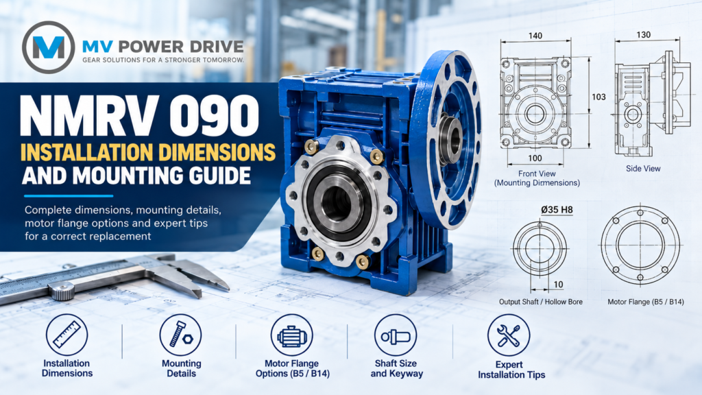
The following measurements come from the 090 column in Motovario’s 2017 VSF IEC/ATEX technical catalogue, section 3.1.2. They are a documented reference example, not a verified specification for every NMRV 090 sold by MV Power Drive or another supplier. Confirm the current drawing for the exact manufacturer, series and configuration being quoted.
| Dimension | Reference drawing symbol | Catalogue reference |
|---|---|---|
| Worm-to-wheel centre distance | I | 90 mm |
| Fixing-centre spacing shown in the main view | A | 140 mm |
| Fixing-centre spacing shown in the end view | K | 100 mm |
| Output-shaft centre height above the illustrated base | H | 103 mm |
| One listed hollow-output bore option | D | 35 mm H8 |
| Keyway width for that 35 mm bore | b | 10 mm |
| Overall width shown in the end view | L | 130 mm |
The same catalogue also lists 38 mm and 40 mm output-bore options for size 090. This is why “NMRV 090 shaft size” should not be answered with one universal diameter. The selected bore and its corresponding keyway must be identified on the order.
Use this table to understand the drawing, not to manufacture a mounting plate without checking the supplied unit. Ask the supplier to mark the selected options on the dimensional drawing and attach that drawing to the quotation. That gives the buyer, maintenance team and supplier the same reference during approval.
How to Check the Mounting Dimensions Against Your Machine
A practical dimensional check starts with the parts of the existing machine that will remain in place. These may include the mounting plate, driven shaft, motor, coupling and surrounding guards. Rather than measuring the gearbox in isolation, prepare a record of the interfaces that the replacement must satisfy. The following approach is useful for organising that information before requesting a quotation.
Check the fixing pattern and shaft position together
Record the distance between mounting-hole centres in both directions, and identify which face of the gearbox is used for mounting. Include the hole diameter or thread specification where it can be established from a drawing or inspection. Avoid recording only the outside dimensions of the housing, because those measurements do not establish where the fixing points sit.
Then record the output-shaft position relative to the mounting surface. Treat the fixing pattern and shaft position as two separate approval checks: matching one does not prove that the other matches. A simple sketch with the mounting surface clearly marked is often more useful to the supplier than several photographs taken from uncertain angles.
For installation, the manufacturer also requires a stable support and a mounting surface that does not distort the gearbox casing when fastened. Do not use the fixing bolts to pull an incorrectly seated gearbox into position.
Record the output connection completely
For a hollow-shaft installation, record the driven shaft’s diameter, key arrangement and available engagement length. Copy the complete bore specification from the proposed drawing, including its tolerance designation, rather than reducing it to a rounded diameter. Also ask how the gearbox will be retained axially and how the installation will be dismantled for future maintenance.
For a solid-shaft arrangement, request the shaft diameter, usable extension, keyway and retaining details. Keep this separate from the hollow-bore specification. Motovario lists output shaft kits, output flanges and torque arms as distinct options, which reinforces the need to identify the actual output arrangement rather than ordering only by housing size.
Check the complete assembly’s installation space
Ask for the dimensions of the motor-and-gearbox combination, not only the bare gearbox. Review the proposed assembly against nearby machine members, guards and access points. Include space for fitting tools, making electrical connections and removing the motor or gearbox later. These are useful installation checks even where the basic mounting holes already match.
For a replacement enquiry, photograph the old assembly before dismantling it and mark any restricted areas on the image. This helps distinguish a gearbox that fits the mounting plate from a complete drive that fits the available machine space. When comparing separate components with complete gear motor assemblies, request the drawing for the exact combination being offered.
NMRV 090 Motor Flange Dimensions: B5, B14 and Motor Frame
The motor connection needs its own dimensional check. B5 and B14 are motor mounting arrangements: B5 uses a larger flange with clearance holes, while B14 uses a smaller flange with tapped holes. The motor frame and flange arrangement must both be identified; “B5 motor” or “B14 motor” alone is not a complete dimensional specification.
For an existing motor, send the supplier its full nameplate and record the shaft diameter, shaft extension and flange dimensions. Ask the supplier to compare the motor’s locating register, fixing pattern and shaft engagement against the gearbox input adapter. Do not assume that an adapter suitable for the motor’s kW rating must also match its mechanical interface.
Our B5 vs B14 flange mounting guide explains the two flange arrangements, while the electric motor frame size chart helps identify the motor information to collect. Keep these checks separate from the gearbox output: the flange joining the motor to the reducer is not necessarily the flange joining the reducer to the machine.
A useful quotation should therefore identify both sides clearly—for example, the required motor input arrangement and the required hollow-shaft or solid-shaft output. This avoids approving a gearbox with the correct output connection but the wrong motor adapter.
Mounting Position and Lubrication
Mounting position describes the orientation in which the gearbox operates, not just the face on which it is bolted down. Motovario’s mounting diagrams include B3, B6, B7, B8, V5 and V6 arrangements. Its installation instructions require the delivered unit to be installed in the specified position, with lubrication and plug arrangements checked against the relevant instructions.
For that reason, do not approve a different orientation simply because another face has usable fixing holes. Send a side-view photograph or sketch showing the motor, gearbox and output shaft in their intended positions. Ask the supplier to state the mounting position on the quotation and confirm the lubricant requirements for that exact unit.
Documentation can differ between product generations. A Motovario datasheet, for example, specifically requires the mounting position to be stated for NMRV 090, while distinguishing other variants in its lubrication information. Use the instructions supplied for the selected model rather than applying a rule from a different NMRV catalogue.
How to Read an NMRV 090 Drawing Without Mixing Up the Dimensions
Start by checking the drawing title, manufacturer, complete model designation and revision. Then identify which views show the motor input, output shaft and mounting surface. Dimension letters are references to that particular drawing; do not assume that a letter copied from one supplier’s catalogue represents the same measurement in another catalogue.
A useful review method is to mark the drawing in three groups: dimensions that connect to the motor, dimensions that connect to the machine, and dimensions that determine installation clearance. Ask the supplier to resolve any unmarked option before approval. This makes the drawing a shared specification rather than a general illustration of the product family.
Keep the dimensional drawing alongside the performance data. Our guide to reading a worm gear reducer catalogue explains how ratio, speed, torque and service factor appear in the technical specification. The dimensional page answers the fitment questions; the performance information answers whether the drive is suitable for the job.
Matching Dimensions Does Not Confirm Torque Capacity
A replacement review should include the machine’s running torque, starting conditions, operating hours and any radial or axial shaft loads. These are separate from the measurements used to establish physical fit. Motovario’s application checklist explicitly requests this operating information alongside mounting position and connection details.
For example, using an assumed motor speed of 1,400 rpm, a 30:1 gearbox produces a calculated output speed of:
1,400 ÷ 30 = 46.7 rpm
That calculation establishes speed, not the gearbox’s allowable torque. The proposed unit still needs an appropriate rating for the actual load and duty. Our conveyor gearbox ratio calculation guide explains the speed calculation, and the service factor guide introduces the duty assessment.
For a new installation, use the NMRV 63, 75 and 90 comparison as a starting point for discussing body-size selection—not as proof that a particular size fits or carries the load. For replacement work, ask whether the original gearbox was correctly selected, especially when the reason for replacement is repeated failure rather than ordinary wear.
A Replacement Example: Same Size and Ratio, Different Fit
Consider a hypothetical conveyor whose existing gearbox is marked NMRV 090 with a 30:1 ratio. The maintenance team records a 35 mm driven shaft and identifies the motor’s flange arrangement. A supplier then offers another size-090, 30:1 unit, but the quotation specifies a 40 mm output bore and a different motor adapter. The size and ratio agree, yet the proposed assembly does not match the recorded connections.
The correct next step is to ask for the required bore and motor adapter, then compare the revised drawing with the existing installation. Do not treat an unspecified sleeve or workshop modification as an automatic solution. Any change to the shaft connection or mounting arrangement needs its own engineering approval.
A written comparison makes this straightforward: existing specification, proposed specification and any unresolved difference. This is also useful when several people are involved in purchasing, because the person approving the price may not be the person who measured the machine.
Does a Bronze Worm Wheel Change the Installation Dimensions?
“Bronze” describes a material used for the internal worm wheel; it is not a complete external mounting specification. MV Power Drive’s NMRV product information lists bronze worm-wheel materials separately from the gearbox body sizes and other specifications. A request for a “bronze NMRV 090” therefore still needs the input flange, output connection and mounting details.
When comparing quotations, keep material information and installation dimensions in separate fields. Ask for the specified wheel material where it matters to the application, but use the approved drawing to establish physical compatibility. Neither a bronze-wheel description nor a similar-looking housing replaces the dimensional check.
What to Send for an NMRV 090 Replacement Quote
Prepare the enquiry around the existing installation rather than sending only the model name. A clear nameplate photograph is the starting point, but photographs of the motor connection, gearbox output and mounting arrangement make the request much more useful. Where an original drawing exists, include it and identify any changes made to the machine since installation.
Send the following information together:
- Identification: gearbox manufacturer, complete model code, ratio and photographs of both gearbox and motor nameplates.
- Connections: output shaft or bore details, motor frame and flange, fixing dimensions and the existing dimensional drawing.
- Installation and duty: mounting position, available space, application, operating hours and starting conditions.
- Supply requirements: gearbox only or complete gear motor, required accessories, quantity and delivery city.
Ask the supplier to return the quotation with the proposed configuration and its drawing. For budgeting, our NMRV gearbox price guide for Pakistan provides size-based ranges, but request the firm price against the exact assembly being approved rather than a generic “NMRV 090” description.
Frequently Asked Questions
What is the output shaft size of an NMRV 090?
Check the selected bore or shaft option rather than assuming one diameter. The Motovario catalogue referenced above lists several output-bore options for size 090. Ask the supplier to identify the chosen bore, keyway and output arrangement on the quotation and dimensional drawing.
Will an NMRV 090 from another manufacturer fit my machine?
Do not approve it from the model designation alone. Compare the existing and proposed drawings, paying particular attention to the mounting pattern, output connection, motor adapter and installation space. Record any differences in writing and ask the supplier to confirm how they will be addressed before placing the order.
Can I reuse my existing motor with a replacement gearbox?
Treat motor reuse as a separate approval check. Provide the existing motor’s frame, flange, shaft dimensions, power and speed, and ask the supplier to confirm the proposed input connection. Keeping the motor does not remove the need to review the gearbox’s output speed, load suitability and physical installation.
Where can I obtain an NMRV 090 drawing or CAD model?
Request the drawing from the manufacturer or supplier for the exact configuration being quoted. Motovario provides access to 2D/3D CAD drawings through its product resources. For a complete gear motor, request the assembly drawing as well as the reducer details so the motor and accessories are included in the installation review.
Confirm the NMRV 090 Dimensions Before Ordering
The most useful replacement specification combines three things: the operating requirement, the mechanical interfaces and the installation arrangement. Keep the nameplate, dimensional drawing and application details together throughout the quotation process. That makes it easier to identify a mismatch before delivery instead of discovering it when the production line is waiting for the replacement.
Contact MV Power Drive with your existing gearbox and motor nameplates, mounting photographs, ratio and shaft dimensions. Ask for the proposed NMRV 090 configuration and drawing to be checked against those details before you approve the order.