
A worm gear reducer specification tells you five things: the reduction ratio, the output speed, the output torque, the input power it can take, and the service factor that links them to your real duty. Read those correctly, plus the mounting position and lubrication, and you can match any catalogue to your machine without guesswork.
This guide walks through each line of a worm gearbox specification, shows a worked example, and ends with a checklist you can send to a supplier.
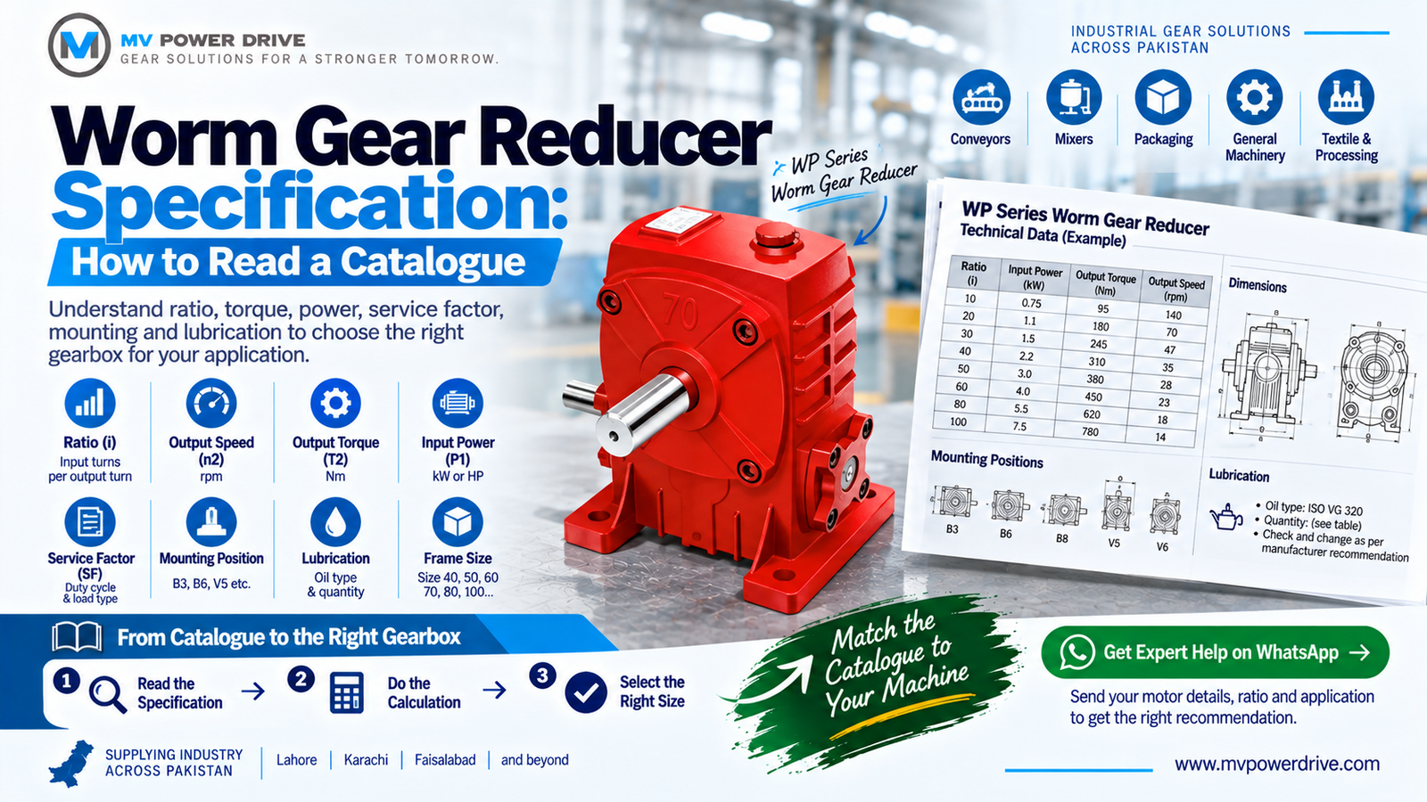
The Key Terms on a Worm Gearbox Specification
| Term | What it means | Typical unit |
|---|---|---|
| Ratio (i) | Input shaft turns needed for one turn of the output shaft, such as 20:1 or 100:1 | Ratio |
| Output speed (n2) | Speed of the output shaft after reduction | rpm |
| Output torque (T2) | Torque available at the output shaft | Nm |
| Input power (P1) | Motor power the gearbox is rated to accept | kW or HP |
| Service factor (SF) | Adjustment for duty cycle, shock loads, starts per hour and running hours | Number, such as 1.25 or 1.5 |
| Mounting position | Orientation of the gearbox, which sets the oil level | Code such as B3, B6, V5 |
| Lubrication | Oil or grease type and quantity | Grade and litres |
| Frame or body size | Physical size, often the centre distance between worm and wheel | mm |
These definitions follow standard nameplate practice (source). Different makers label them slightly differently, but the meaning is the same.
Ratio and Output Speed
Output speed is the motor speed divided by the ratio. A standard 4 pole motor runs near 1400 rpm, so a 30:1 reducer gives about 47 rpm at the output. If you are working back from a machine speed, our guide to calculating gearbox ratio for a conveyor drive shows the full method.
Worm gearboxes cover a wide ratio span in one stage. MV Power Drive lists single stage ratios from 1:5 to 1:100 on the WP series, and double reduction units for far higher ratios when you need very slow output.
Output Torque and Input Power
Torque is what the machine actually feels. The usual relationship is:
Output torque (Nm) = 9550 x motor power (kW) x efficiency / output speed (rpm)
Efficiency matters more in worm gearboxes than in helical ones, because the sliding contact between worm and wheel wastes some power as heat. Efficiency falls as the ratio rises, so always read the catalogue value for your exact ratio and size.
Service Factor
Catalogue torque assumes smooth, steady loading for a limited number of hours. Real plants have shock loads, frequent starts and 24 hour shifts. The service factor scales the rating up to cover that. Multiply your calculated torque by the service factor, then pick a gearbox whose rated torque is at or above the result. We cover the factor in depth in service factor in gearbox selection.
Worked Example
A belt conveyor uses a 1.5 kW, 4 pole motor at 1400 rpm and needs about 47 rpm at the drive shaft.
- Ratio: 1400 / 47 is about 30, so choose a 30:1 reducer.
- Output speed: 1400 / 30 gives 46.7 rpm.
- Output torque: 9550 x 1.5 x 0.80 / 46.7 is about 245 Nm. The 0.80 efficiency is an assumed illustration, so use the catalogue value.
- Service factor: the conveyor runs two shifts with moderate shocks, so use 1.5. Required rating is 245 x 1.5, about 368 Nm.
- Pick a frame whose rated output torque at 30:1 is at least 368 Nm for 1.5 kW input.
If the catalogue lists a smaller size at 300 Nm, it is too small once the service factor is applied, even though it looks fine on the raw torque.
Mounting Position and Lubrication
Mounting position decides where the oil sits relative to the worm and bearings. A gearbox ordered for one position and installed in another can run dry in places. Specify the position when you order, and match the motor flange as well, using our B5 vs B14 flange guide if you are unsure.
Many small worm units are filled for life, while larger cast iron units may need oil checks and changes. See gearbox oil change interval and grade for service schedules.
Reading MV Power Drive WP Series Data
As an example of how to apply the above, the WP series worm gear reducer is listed with:
- Cast iron housing
- Worm wheel in tin bronze, aluminium bronze or copper alloy, chromium steel shaft with a surface hardness of 56 to 62 HRC
- Input power from 0.06 kW to 15 kW
- Body sizes 40, 50, 60, 70, 80, 100, 120, 135, 147, 155, 175, 200 and 250
- Single stage ratios 1:5 up to 1:100 and double stage ratios from 1:200 upward
For smaller aluminium bodied units, compare the NMRV series and our NMRV size guide. The full range of reducers is on the gear reducers page.
Checklist: What to Send a Supplier
- Motor power, voltage, phase and speed
- Required output speed or ratio
- Load torque and type of load (steady, shock, reversing)
- Running hours per day and starts per hour
- Mounting position and shaft arrangement
- Ambient conditions: heat, dust, washdown
Send these details to MV Power Drive and we will confirm the frame size, ratio and torque rating against the catalogue.
Frequently Asked Questions
What are the main specifications of a worm gear reducer?
Ratio, output speed, output torque, input power, service factor, mounting position, lubrication and frame size.
How do I calculate the output torque of a worm gearbox?
Multiply 9550 by motor power in kW and by efficiency, then divide by output speed in rpm. Apply the service factor afterwards to find the rating you need.
What service factor should I use for a conveyor?
It depends on load and hours. Smooth, single shift duty is often 1.0 to 1.25, while heavy or 24 hour duty is higher. Confirm against the maker’s table.
What does the ratio 1:30 mean on a gearbox?
The input shaft turns 30 times for one turn of the output shaft, so output speed is the motor speed divided by 30.
Why does efficiency drop at higher ratios in a worm gearbox?
Higher ratios use a finer worm lead, which increases sliding friction between worm and wheel and turns more input power into heat.
Where can I get a worm gear reducer catalogue in Pakistan?
Contact MV Power Drive in Lahore for catalogue data, sizing help and quotations for worm reducers.